Contact Us

You are here:

Core Barrel Roller Bit

The single roller bit is used as an accessory, which is installed on the barrel drill alternately. It is mainly used in the pile foundation construction of municipal bridges and buildings, and is mostly used in coastal areas.
CORE BARREL ROLLER BIT collection

PRODUCT OVERVIEW

The rock-breaking principle of the rotary barrel drill is to form a broken ring by alternating inner and outer roller bit, then break rocks through extrusion, shearing and impact. Finally, break the rock core in the middle of the barrel bit by oscillating the barrel bit, and form the holes required for the construction after the rock core is taken out.
CORE BARREL ROLLER BIT product feature

PRODUCT MAIN FEATURES

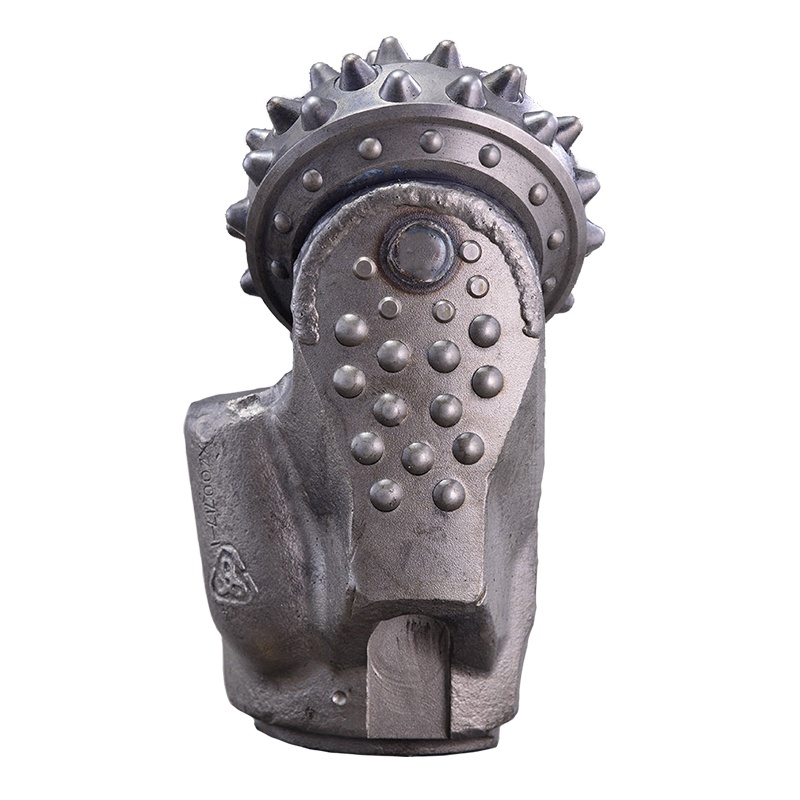
The O-shaped rubber lip is used to seal the large- diameter bearing
structure, which improves the bearing capacity and
effectively
improves the service life of the drill bit bearing;
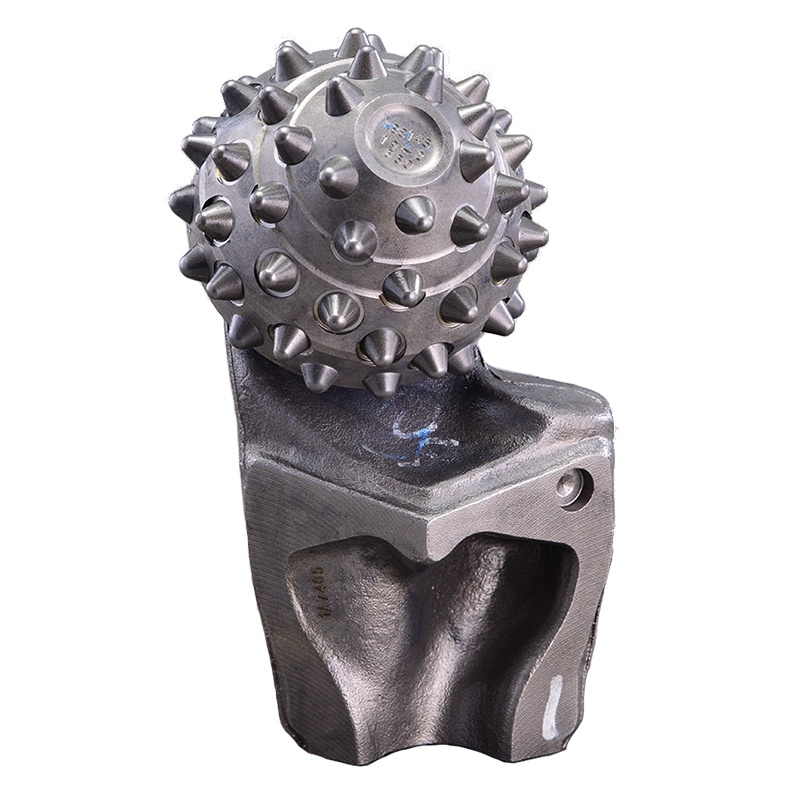
Large-diameter cones and U-shaped bottom hole cutting mode
improve cutting efficiency and the stability of the bottom hole
operation of the drill bit
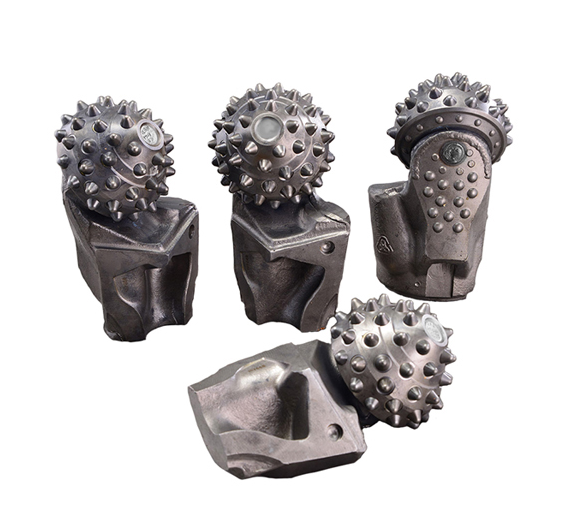
It can meet the needs of 1 20mm in width.

2 1

Barrel bit’s pull down: 20~30t (Independent maximum pressure is 5~7t per unit.)

Formation pull down Rotation speed
Hole diameter Rotation speed
Medium hard(50-100Mpa) 20-30t 0.8-1.5 12-16
1.5-2 10-12
2 -2.5 6-10
2.5-2.8 3-6

Hard

(80-150Mpa)

20-35t 0.8-1.5 10-12
1.5-2 8-10
2 -2.5 5-8
2.5-2.8 2-5

Note: Within the same interval, the larger the borehole diameter, the lower the rotational speed. The single bit piece of the rotary digging roller bit can withstand a rated pull down of 5-7 tons/piece, and the rated speed range of the roller cone is 60-100 rpm.

WELDING INSTRUCTIONS

tuceng26 Description: The installation of the rotary bit is divided into inner and outer staggered installation
  • Drill bit material: 15CrNiMn
  • Welding process:
  • Welding method: mixed gas shielded welding
  • Welding wire: ER50-60
  • Welding wire diameter: Φ1.2mm
  • Welding current: 280~340A
  • Voltage: 25~35V
  • Protective gas: 80%Ar+20%CO2
  • Gas flow: 15~20L/min

1) According to different diameters, install the corresponding number of cones to ensure the maximum cutting outer diameter of the cones.
2) Cutting width 115≤L≤120mm.
3) The welding installation angle is controlled at 3°~5° (the lug back is away from the well wall).
4) The exposed height difference of the welding cone is controlled within 3mm.
5) Welding precautions: During the welding process, prevent the arc from burning the roller bits or carbide inserts. Take cooling measures for the roller bits (compressed air cooling, water cooling or wrapping the rollers with wet towel for cooling, to ensure that the roller bearing temperature does not exceed 100ºC).

PRODUCT DISPLAY